I enjoy working with wood. When I work with wood I may use a hammer. However, if I were building a project and I was limited to using only a hammer, the project is doomed to failure. Without additional tools, such as a saw, a square, and some method for fastening pieces together (glue, nails, screws) not even the most basic structure could be fashioned. So, why should we believe one tool is adequate to predict and prevent complex machine problems?
This article presents an example of how the use of vibration analysis in the form of route-based collection of vibration data gives warning of an increasing machine problem. The machine was a 600-hp 4,160-V motor driving a clarified water pump coupled with belts, and the timely use of dynamic electrical testing, followed by infrared thermography and visual inspection of the machine components, are shown working together to diagnose and confirm a rotor bar problem. This pump operates in a coal prep plant.
During regular route-based collection of vibration data, the data collected from the pump motor showed elevated impacting in both the spectrum and the waveform data. The amplitude at 29.75 Hz (1×TS) in the spectrum was 0.449 in/sec Peak (see Figure 1). Initially, the perceived problem was thought to be belt related. Sidebands surrounding the 1×TS peak are visible.
The history of the machine went back eight months, with the overall amplitude and 1×TS amplitude on the motor climbing each month. The spectrum shown has overall amplitude of 0.526 in/sec Peak. The accompanying PeakVue data from this survey indicates excessive impacting (see Figure 2) and is also related to the turning frequency of the motor.
The waveform data collected from the motor opposite drive end in the horizontal orientation, both velocity (Figure 3) and PeakVue (Figure 4), had reached excessive amplitudes of vibration. Based on these data, it was recommended that the alignment, belts, and sheaves be inspected and repairs made as needed.
Two months later, complaints were made that the same machine was running roughly. The complaints were reported just prior to regular monthly route vibration data collection. Due to the continuing nature of the complaint, the data setup was examined, and the data resolution for that machine was significantly increased.
Data was collected from the machine, and vibration amplitude had increased again (see Figure 5). The increased resolution, to 12,800 lines of resolution with an F-max of 2,100 Hz, revealed multiple sidebands evident and obviously surrounding not only the 1×TS peak, but also surrounding harmonics of turning speed out to the eighth order or more (see Figures 5 and 6).
Reviewing the data showed the sidebands to be at the motor’s slip frequency times the number of poles (i.e., pole pass frequency). These data are an indication of cracked or broken rotor bars. A test expected to confirm or disprove the diagnosis of broken or cracked rotor bars is current signature analysis (CSA), so it was arranged to collect this data the following day from the 4,160-V electric motor using a current clamp input to an Emerson CSI 2130 data collector. Additional high-resolution vibration data was collected as well.
The current signature analysis data showed a dB difference of 29.83 dB amps (see Figure 7). Rotor bar problems are suspected at 45 dB amps or less. The motor was removed from service, disassembled, and inspected.
Note: Potential transformers (PTs) were not available in the control voltage cabinet at the motor control center, which made the current clamp the ideal choice to collect the data. Had PTs been available, dynamic electrical data could have been collected which could have provided more information regarding power and torque.
With the rotor removed from the motor stator, it is possible to apply a current load on the rotor (on an AC induction motor) to simulate startup. This process allows an additional test to confirm the presence of cracked or broken rotor bars: infrared thermography can be used to show areas of high-resistance heating on the rotor.
The removed cast aluminum rotor was placed in stands and had a 1,000-amp low-voltage current applied while the rotor was surveyed using infrared imaging. Several hotspots were noted that were concentrated at the end ring connection areas (see Figure 8), and heating was observed between the shaft spider and the inside of the rotor (see Figure 9). Close visual inspection of the rotor also revealed areas which had seen excessive heating from cracked or broken rotor bars (see Figure 10).
At this point in the analysis, three separate predictive maintenance (PdM) technologies all pointed to the same problem in this machine:
- We first noticed a problem in the route vibration data, and increased the resolution which showed the problem to be highly likely.
- We followed that with Current Signature Analysis which confirmed the problem, after which we removed the motor from service before any additional damage could be done to the machine train or motor stator.
- Once disassembled, infrared imaging was used to further confirm and refine the problem with the rotor which could be visually noted when viewed closely.
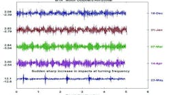
Following repair, the next time that route-based vibration data was collected from the machine, the vibration was within acceptable limits. The overall vibration was reduced, the motor 1×TS vibration was reduced, and the excessive waveform amplitude was eliminated (see Figure 11).
Should one technology be used exclusively in diagnosing machinery problems? Definitely not! We have a number of tools available for our predictive toolbox. Not a single one of them is well served by ignoring all others.
Vibration, thermography, electrical testing (both dynamic and static), ultrasound, and tribology all work together to reduce or eliminate catastrophic failures, and allow for the most reliable plant operation possible. And never forget that some of the most valuable tools available are the eyes and ears of those who normally come in contact with the machine.
