Preventive maintenance is a predetermined task performed based on a schedule and its objective is to keep equipment in good condition to avoid breakdowns. With properly scheduled monitoring and data collection, this testing can be very useful in analyzing and predicting the current and future behavior of equipment. Early problem detection helps avoid major repairs, resulting in cost savings when compared to a run-to-failure maintenance practice. Preventive maintenance has the added benefit of pre-planning for necessary parts and resources.
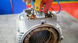
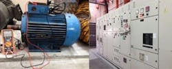
This article describes the insulation resistance testing method commonly used for preventive maintenance activities. Insulation resistance testing is commonly performed as part of electrical testing in a preventive maintenance program for rotating machines, cables, switches, transformers, and electrical machinery where insulating integrity is needed. Insulation resistance testing in the preventive maintenance program helps identify potential electrical issues to reduce unpredictable, premature equipment repair and replacement cost (see Figure 1).
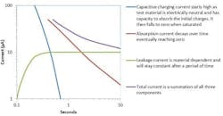
Insulation resistance is used to verify the integrity of the insulation material, whether cable insulation or motor/generator winding insulation. Insulation resistance testing is carried out by applying a constant voltage to the equipment under test while measuring the flowing current. High DC voltage is used, causing a small current to flow through the insulator surface. The total current consists of three components (see Figure 2):
- Capacitance charging current: relatively high upon start-up, drops exponentially within a few seconds to dozens of seconds. It is normally negligible when the reading is taken.
- Absorption current: decays at a decreasing rate. It may require up to a few minutes to reach zero depending on the insulation materials.
- Leakage current: constant over time.
For an effective test, results should be regularly recorded over a period of time and compared with earlier recorded values taken when the equipment was new and in good condition. The trend of the readings over a period of time will help identify the presence of anomalies. Insulation resistance values that are consistent over time indicate that the equipment’s insulation properties are good. If the resistance values are decreasing, it indicates that potential issues can occur sometime in the future and more thorough preventive maintenance should be scheduled soon.
Factors that affect the insulation resistance
The factors that commonly affect the insulation resistance are:
- Surface condition. For example oil or carbon dust on the equipment’s surface that can lower the insulation resistance.
- Moisture. If the equipment’s surface temperature is at, or below, the dew point of the ambient air, a film of moisture forms on its surface would, lowering the equipment’s resistance value.
- Temperature. The insulation resistance value may vary inversely with the change of the temperature. Its influence on readings can be mitigated by performing preventive maintenance testing at the same temperature each time. If the temperature cannot be controlled, normalizing to a base temperature such as 40 °C is recommended. This is commonly done using the estimation rule, “Every 10 °C increase in temperature halves the insulation resistance, while a 10 °C reduction doubles the resistance”. As different materials may have different degrees of resistance change due to temperature, for more precise temperature correction, some may adopt a temperature correction factor; the measurement reading should be multiplied bythe temperature correction factor at the corresponding temperature.
What are the test methods for insulation resistance test?
There are three types of tests for measuring insulation resistance, and each test applies its own methodology that focuses on a specific insulating property of the devices being tested. Users need to choose the one that best fits the test requirements.
Spot test: This test is suitable for a device with a small or negligible capacitance effect, e.g. short wiring run.
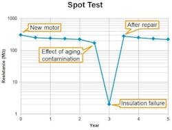
A test voltage is applied for a short interval until a stable reading is achieved, or for a fixed period of time, normally 60 seconds or less. The reading is collected at the end of the test. For the historical record, a chart is plotted based on the history of the readings. Observation of the trend is taken over a period of time, normally over years or months (see Figure 3).
This test is normally performed for Go/NoGo testing or historical records. Temperature and humidity variations may affect the readingsand have to be compensated for if necessary.
Time-resistance test: This test is suitable for the predictive and preventive maintenance of rotating machines.
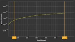
Successive readings are taken at a specific time, typically every few minutes, and difference in readings compared. Good insulation will show a continual increase in the resistance value. If the reading is stagnant and it does not increase as expected, the insulation may be weak and attention may be needed. Moist and contaminated insulation may lower resistance readings since they will increase the leakage current during testing. The temperature influence on this test is negligible as long as there is no significant temperature change in the device under test.
The polarization index (PI) and dielectric absorption ratio (DAR) are commonly used to quantify the time-resistance test result.
Polarization index (PI)
The polarization index is defined as the ratio of the 10 minute resistance value to the 1 minute resistance value. The interpretation of the value is shown in Table 1. The IEEE Std 43-2000 recommends the minimum value of PI for AC and DC rotating machinery in thermal class B, F and H as 2.0, and the minimum PI value for class A equipment is 1.5.
NOTE: Some new insulation systems have a faster response to the insulation test. They usually start with test result at GΩ range yielding a PI between 1 and 2. In these cases, the PI calculation may be disregard. According to the IEEE Std 43-2000, if the 1 minute insulation resistance is above 5 GΩ, the calculated PI may not be meaningful.
Dielectric absorption ratio (DAR)
Dielectric absorption ratio is referred to the ratio of the 60 second resistance value to the 30 second resistance value. The interpretation of the value is shown in Table 1.
DAR is suitable for devices with insulation materials in which the absorption current decreases quickly.
Step voltage test: This test is particularly useful when the rated voltage of the equipment is higher than the available test voltage generated by the insulation resistance tester.
Different voltage levels are applied in steps to the device under test. The recommended ratio of the test voltage is 1:5. The test at each step is same length, usually 60 seconds, and goes from low to high. This test is normally used at test voltages lower than the rated voltage of the equipment. The rapid increase of the test voltage level creates additional stress on the insulation and causes the weak point to fail, subsequently leading to a lower resistance value.
Test voltage selection
As the insulation resistance test consists of high DC voltage, the appropriate test voltage has to be selected to avoid over stressing the insulation, which may lead to insulation failure. The test voltage also may vary according to the international standards. Consulting the product/equipment manufacturer for the proper test voltage values is recommended.
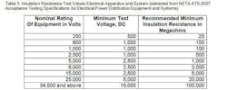
If the appropriate test voltage is not specified by the manufacturer, industrial standards and practices may be applied. The following guideline for rotating machinery shown in Tables 2 and 3 may be adopted in the absence of manufacturer’s data.\
Determination of minimum insulation resistance
The IEEE Std 43-2000 indicates that the minimum insulation resistance for AC and DC machine stator windings and rotor windings can be determined by:
Rm = kV + 1
Where,
Rm is the recommended minimum insulation resistance in MΩ at 40 °C of the entire machine winding (see Table 4), and
kV is the rated machine terminal-to-terminal voltage in kV unit
Safety consideration
As insulation resistance testing involves high DC voltage application, the following safety precautions should be taken:
- Make sure that the device under test is discharged.
- Conduct the test at the de-energized condition to ensure that no test voltage other than that from the insulation resistance tester is applied.
- Restrict personal access when high voltage testing is being conducted.
- Use of personal protective equipment (e.g. protective gloves) where applicable.
- Ensure suitable test leads are used and that they are in good condition. Using unsuitable test leads not only contributes to errors in readings, they may be hazardous.
After the test, make sure the device is fully discharged. This can be done by shorting the terminal with a suitable resistor. A minimum discharge time of four times the applied voltage duration is recommended. Some insulation resistance testers may have the built in self discharge circuit to ensure a safe discharge after the test. Testers with this feature ensure devices are safely discharged after every test.
Planning for a maintenance program
When planning for a maintenance program, equipment that needs maintenance needs to be identified, and priorities set accordingly. A motor or machine that supports the whole line should be a high priority. The frequency of checks to be conducted should also be defined. The frequency can be varied from unit to unit depending on the criticalness of the unit in the environment. Past history will be a good guide for determining when the next maintenance activities will be needed.
The maintenance record should cover the following:
- Date of the test
- Test voltage and current
- Test time
- Insulation resistance value
- Temperature of winding/equipment
- Identification of the equipment/device under test
- Parts or equipment that were included in the test
- Relative humidity
As with every preventive maintenance program, record keeping and plotting of consecutive readings can identify trends and enable you to predict and plan for the next action.
In sum, Periodic testing is the best approach for preventive maintenance of electrical equipment, and charting result values helps in monitoring the trend of the insulation resistance, which helps predict the future need for action.
