In brief:
- Consider piping anytime you change your compressed air system
- A powerful driver leading to piping-system problems is the cost of installation.
- Following best practices in sizing piping can save you money and help optimize the operating of your compressed air system.
The installation of the piping system is often a forgotten element in compressed air system design, but piping problems can have a big effect on how well your system performs. Much attention is placed on the actual first cost of the compressed air equipment and the efficiency characteristics of the main system equipment such as compressors and dryers, but decisions on the pipe sizing and routing are often left to others, and they might not have your best interests in mind.
Why design is typically left to others
A powerful driver leading to piping-system problems is the cost of installation. Hiring a system engineer to size and lay out the piping stretches already thin budgets and is often looked upon as an unnecessary expense. But plant personnel are typically generalists, having a broad knowledge of their field, but often having little specific compressed-air-system design skills. Plant personnel are usually very busy individuals with barely enough time to perform their normal duties, let alone research and design a compressed-air system. So, these duties are usually passed on to the seller of the compressed air equipment as part of a turn-key package price.
These equipment providers are often under budget pressures of their own with their managers looking for them to turn a profit on the sale and installation of this equipment and to do it as quickly as possible. Sometimes the equipment vendors no have designers or pipefitters on staff to assist with the system layout and sizing. Too often the pipe installation is subcontracted out to the lowest bidder with only general instructions given to install the compressor and dryer. In many cases, the responsibility for the layout and design then falls on a contractor or in worst cases his helper, with instructions to do it in the least expensive manner possible.
When it comes to cutting costs, the pipe size is one of the first items to be adjusted. If nobody specifies the size and how the piping is to be run, then it is up to the person who installs the piping. And, if he is the one paying for the pipe on a fixed-price job, there is a chance the piping system will end up too small.
What’s at stake
A rule of thumb in the compressed air system energy field is that, for every 2 psi increase in compressed air pressure, the compressor energy cost increases by 1%, at a pressure of around 100 psig. Undersized or poorly laid-out piping forces compressor discharge pressures to rise to compensate for excessive pressure differential. In a normal plant, there will be a number of critical pressure end uses that need a consistent pressure of, for example, no lower than 90 psi or production will be affected. If there is a 20 psi pressure differential in the system piping, then the compressor discharge pressure needs to rise at least 20 psi to ensure the minimum pressure is maintained at the critical user. This rise costs an additional 10% in energy costs at the compressor.
But there are additional costs that may come into play. In piping systems, the maximum pressure differential and the resulting lowest pressure at the end user happens only during system peaks. In most cases this maximum pressure differential appears only during a small fraction of the total system operating hours, and yet the system pressure is maintained at an artificially high pressure all the time to compensate for the occasional peaks. And the higher pressure acts on unregulated air demands that are pressure sensitive, causing them to consume a little less than 1% more air for every 1 psi increase. This high pressure typically does not result in improved production at the end use, but the additional flow, called “artificial demand,” further increases electrical costs.
Compressor control can be affected
[pullquote]In addition to this, the control of air compressors can be negatively affected by the differential pressures caused by undersized piping. This is more of a factor when dealing with lubricated screw compressors that run in load/unload mode because, in the “load” condition, the compressor passes full flow creating maximum pressure differential in its associated piping each cycle. Excessive pressure differential between the compressor and the system storage compressor can cause rapid cycling of the compressor and drive down-unit efficiencies significantly. For example, a 5 psid piping differential will almost double the frequency of compressor cycles on a compressor set for a 10 psi wide pressure band setting. Excessive cycle frequency wears out the compressor prematurely and increases energy consumption.
An example of the costs that might be incurred for a continuously operating (8,760 annual hours) typical 100 hp compressor at 65% load and at 120 psi and $0.10/kWh power cost would be around $60,000/year. At a lower discharge pressure of 100 psi, reduced artificial demand, and optimized cycle frequency, the operating costs would fall to about $46,100/year for a savings of 23% worth $13,940 per annum. That kind of savings over 10 years could buy a lot of pipe.
CAC recommendations
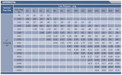
Piping pressure differential formulas are quite complex and often confusing; therefore, many tables have been developed by numerous sources to use as tools for sizing compressed air piping. These tables can readily be found in typical reference books and on the Internet and can be used to estimate approximate pressure differentials at various pressures, flows, and atmospheric conditions. An example from the Compressed Air and Gas Institute (CAGI) for 2-in. Schedule 40 steel pipe is attached in Figure 1.
Figure 1. CAC recommends that the pressure differential across the complete compressor air piping distribution system from the compressor discharge to the end use, before end-use filters and regulators, should be kept less than 10% of the compressor discharge pressure.This shows a typical pressure diffential table using CAGI data. (Source: Air Power USA)
When specifying pressure differential, the Compressed Air Challenge (CAC) recommends that the pressure differential across the complete compressor air piping distribution system from the compressor discharge to the end use, before end-use filters and regulators, should be kept less than 10% of the compressor discharge pressure. This differential includes compressor room air dryers and filters, typically accounting for 5-6%. This means that piping should be designed for no more than 4-5% pressure differential at peak flows, preferably less.
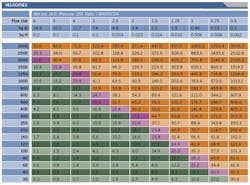
Figure 2. The CAC has come up with desired maximum pipeline velocity levels as a guide to best practices in piping.
To simplify the sizing and to optimize pressure differentials, the CAC has come up with desired maximum pipeline velocity levels as a guide to best practices in piping (Figure 2):
- No more than 20 ft/sec in compressor room headers
- No more than 30 ft/sec in the distribution header, less where long lengths may cause excessive pressure differential
- No more than 30 ft/sec in piping drops based on peak end use flows.
The simple formula to calculate pipeline velocity:
V (fps) = Q (cfm) ÷ A (ft2) ÷ CR ÷ 60 (seconds/minute)
Where:
Q = cubic feet per minute referenced to compressor inlet conditions
A = internal area of pipe in square feet from piping specifications,
CR= compression ratio (psia in pipe ÷ psia atmosphere at site).
Example:
A 100 hp compressor produces 444 cfm at 14.5 psia atmospheric pressure. What is the velocity of air in a 2-in. Schedule 40 steel pipe?
V = 444 ÷ 0.0233 ÷ (114.5 ÷ 14.5) ÷ 60 = 40.3 fps
This pipe size would be unacceptable for a compressor room header or distribution header for this size of compressor. Note that Figure 1 shows acceptable theoretical pressure differential, but this does not account for losses due to fittings, directional changes, air entry points, and other effects inside the compressor room.
For 3-in. pipe:
V = 444 ÷ 0.0579 ÷ (114.5 ÷ 14.5) ÷ 60 = 16.2 fps
This would be an acceptable size and would present minimal pressure differential under all conditions.
Best practices manual
More information about sizing piping can be found in CAC’s Best Practices for Compressed Air Systems Manual available on the CAC website. Selection of this larger piping size would decrease the pressure differential in the compressor room by a factor of more than 7. Also, most compressors in the 100-hp range come with 2-in. outlet port sizes and that air dryer and filters sized for this compressor would also have similar inlet and outlet sizes. When arranging piping, it is often tempting to simply install the same size piping as the compressor port size; however, this may result in excessive piping velocities. This standard pipe size offered by the manufacturer is typically due to economics in manufacturing the compressor rather than being chosen to optimize pressure differential in a real compressed air system.
Example of pressure differential
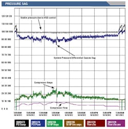
It is common these days for a customer to purchase a very efficient VSD-controlled compressor to save energy and to accurately control the plant pressures. Often, however, the benefit of this very precise control is lost due to poor piping and clean-up equipment sizing. Figure 3 shows how a 50-hp VSD controls the pressure very accurately maintaining a precise pressure level of 99 psi at its discharge. Unfortunately, due to the characteristics of the components located between the compressor and the plant, a 15 psid pressure drop appears during peak production loading. This high pressure differential occurs when the compressor is only half loaded. If full loading is even possible, the pressure differential will be very high, causing production issues.
Figure 3. Differentials cause a sag in system pressure forcing pressure to rise.
Additional piping recommendations from CAC
- When connecting compressors to the compressor room header use 45° entries, rather than 90° fittings that cause excessive pressure differential.
- Never place an entry point where two different flows of air oppose each other; this is a recipe for significant pressure differential.
- Be aware that fittings, valves, and any other component that changes the path of the air flow will cause a pressure differential and should be accounted for in designing your piping.
- When initially purchasing and installing pipe, be sure to size for the future and additional growth.
- When adding compressors, check your piping size to ensure it is still adequate.
- Size your piping for the worst case scenario with all compressors running.
- Plastic piping is not recommended for compressed air, due to low temperature ratings and possible chemical reaction with some compressor lubricants.
- When laying out piping, consider loop systems where economical; the addition or a second parallel path reduces system flow by half and reduces pressure differential by four times for a 75% reduction.
- When saving pressure differential using smooth bore aluminum, copper, or stainless steel piping, remember if you use the equivalent smaller size piping you get the same pressure differential as with standard pipe. Use of the same size piping as before, but with smooth bore, will gain savings.
| Ron Marshall is a member of the Project Development Committee at the Compressed Air Challenge. Contact him at [email protected] and (204) 360-3658. |
Consider piping anytime you change your compressed air system. Poor attention to the sizing and layout of piping can increase operating costs significantly. Don’t leave piping design up to your vendor or pipe fitter. Following best practices in sizing piping can save you money and help optimize the operating of your compressed air system.


